Control high power LEDs (1W, 3W) from the APM 2.5 LED output
I was looking for a way to make the ARM and GPS LED signals more visible for quite a while. Ideally, I thought, I could drive high-power LEDs somehow from that outputs. A short question in the comments of my blog post with the LED poles at DIY-Drones didn’t yield any results except the reflex-like pointing to the jDrones JDIO board.
Well, I do have a JDIO board and it’s not usable for that purpose at all.
Reasons:
- The JDIO board is not a LED driver. It’s basically just a switch with an Arduino attached. Primary function of a LED driver is to supply a constant current, not to switch stuff on and off
- The JDIO board has a current limit of 500mA per channel. That works for 1W LEDs but nor for 3W LEDs.
- The JDIO board does decode MAVlink but the (IMHO) most interesting and important infos, i.e. ARM and GPS status, are not evaluated.
So, I started googling and scanning eBay. On eBay I found an interesting assortment of LED drivers from a German supplier - KT-Electronic. I ordered a few drivers and a bunch of other stuff and sent the seller a question about how the driver likes being dimmed by PWM on the supply side. Within a couple of hours I received an email, pointing me to another driver. The email described the circuitry and included the datasheet for the IC that’s used on those driver. Actually, the seller has 2 drivers with this chip, one configured to drive 1-3x 1W LED in series and one configured to drive 1x 3W LED.It turned out, that those ICs have a combined analog/PWM input to control the LED output. Analog/PWM combined? Yeah! You can either apply between 0.2 and 5.0V to the ADJ input, which will result to proportional dimming of the output, or send a PWM signal with 0 and 5V amplitude.
This is the module before the modification:
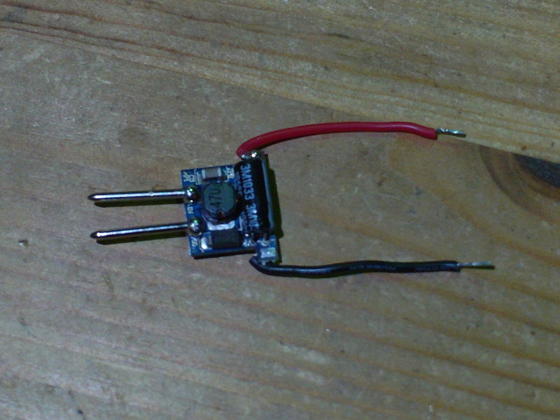
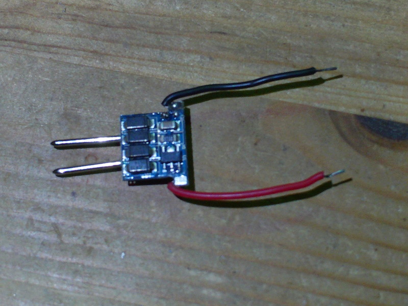
The SN3350 is easily accessible (latter photo, bottom right). All that needs to be done is to solder a servo cable to ADJ (bottom right pin) and GND (bottom center pin) and replace the MR16 pins with some cables. Soldering the cables to the IC requires somewhat of a steady hand but it’s totally doable.
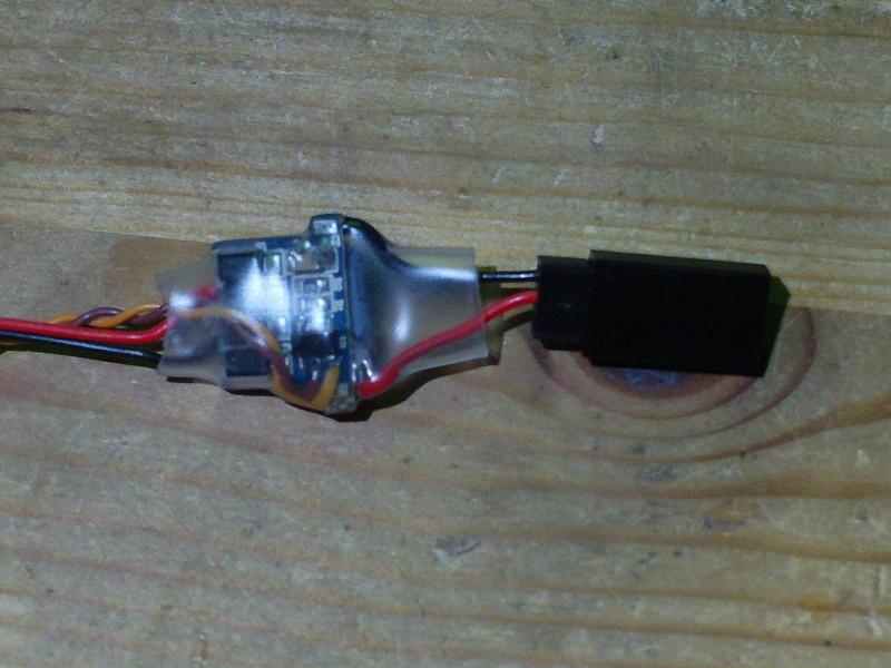
This is the module after the modification:
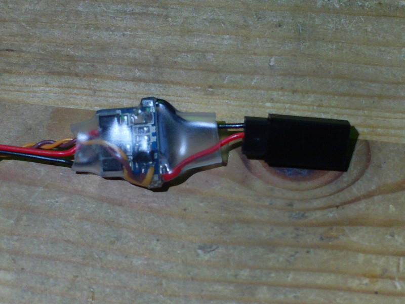
Now you only have to connect the supply line to the battery and the control line to the APM and you have the APM controlling up to (3) 1W high-power LEDs. Don’t forget the cooling for the LEDs!
According to the seller, the boards are tested up to 24V supply voltage. The IC can do up to 40 volts but the capacitors are only 25V types. The eBay auction does say 12V for one and 6-16V for the other but that is the normal operating voltage or (in the latter case) the minimum voltage (16V for 3 LEDs). I already tested the modules with a 4S LiPo a couple of hours constant operation and they didn’t get noticeably hot.